Shift registers
A row of flip-flops wired output to input, all on one clock. Every edge, the contents move along by one place. That one sentence covers everything on this page.
Stage k is the input, k+1 cycles ago
Each flip-flop takes whatever its neighbour was holding when the edge arrived, so every stage gets the old value of the one before it, not the new one, and the data moves exactly one place per edge rather than racing to the end.
What actually stops the race is a delay, not simultaneity: a flip-flop takes time to change its output after the edge, and by then its neighbour has already captured the old value. That is also why clock skew along a long register is dangerous — let one stage see the edge late enough and it captures its neighbour's new value, and a bit vanishes.
| Cycle | IN | Q0 | Q1 | Q2 | Q3 |
|---|---|---|---|---|---|
| 1 | 1 | 0 | 0 | 0 | 0 |
| 2 | 0 | 1 | 0 | 0 | 0 |
| 3 | 1 | 0 | 1 | 0 | 0 |
| 4 | 1 | 1 | 0 | 1 | 0 |
| 5 | 0 | 1 | 1 | 0 | 1 |
| 6 | 0 | 0 | 1 | 1 | 0 |
| 7 | 0 | 0 | 0 | 1 | 1 |
| 8 | 0 | 0 | 0 | 0 | 1 |
Read a column downwards and you see one bit travelling. Read a row across and you see the register's contents at that moment, which is what a parallel output gives you all at once.
Four ways to wire the ends
The chain is always the same. What changes is whether you put data in one bit at a time or all at once, and whether you read it the same way. Those two choices give four registers, and the names are just the two answers written down.
| Register | In | Out | What it is for |
|---|---|---|---|
| Serial in, serial out SISO | one bit per clock | one bit per clock | A delay line: whatever goes in comes out a fixed number of cycles later. |
| Serial in, parallel out SIPO | one bit per clock | all stages at once | Receiving. A byte arriving one bit at a time on a single wire ends up on eight, which is what the receiving half of a UART does. |
| Parallel in, serial out PISO | all stages at once | one bit per clock | Sending. Load a whole word, then clock it out down one wire. |
| Parallel in, parallel out PIPO | all stages at once | all stages at once | Storage: a register in the ordinary sense, holding a word for one clock or many. |
Feed the end back and it counts
Wire the last stage to the first and the register stops being a pipe and becomes a loop. Load a single 1 and it walks round for ever: four stages, four states, and each state is already one wire, so nothing needs decoding. That is a ring counter, and it is the cheapest way to drive things that must happen in strict rotation.
Invert on the way back instead and the register fills with 1s, then empties again. The same four flip-flops now give eight distinct states, twice the ring's, for the cost of one inverter in the feedback.
Neither counts in binary, so neither is a substitute for a binary counter when you want a number. What they buy is a cheap decode. A ring counter needs none at all, because each state is already one wire. A Johnson counter is not one-hot, so it does need gates — but only one two-input gate per state, against the n-input gate a binary counter needs, and the decode is free of the glitches a rippling binary count produces.
Both have a catch worth knowing: neither is self-correcting. A four stage ring has sixteen possible states and only four of them are on the ring, so a bad power-up or a single upset leaves it circulating in a loop it can never leave. The Johnson counter has a second closed loop of its own, 0101 → 1010 → 0101. Real designs either force a known state at reset, or replace the plain feedback with a gate that steers any illegal state back into the sequence within n clocks.
Building one
A shift register is the one sequential circuit with nothing clever in it: D flip-flops in a row, output to input, one shared clock. If you have built a D flip-flop you have built a shift register; the only decision left is how many.
Reference cards
All three waveforms as images, black on white, for notes or a slide.
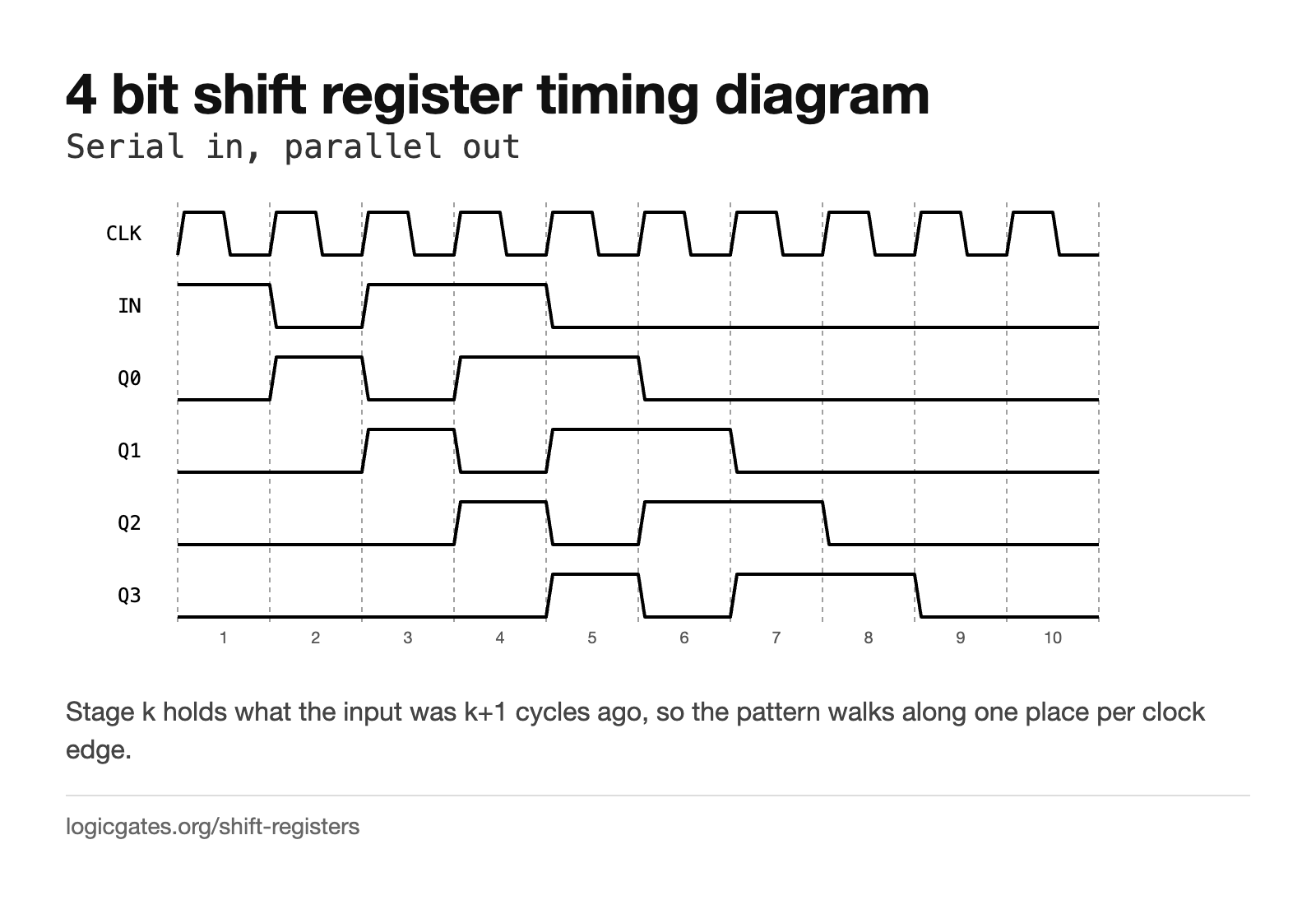 Click to download: 4 bit shift register timing diagram
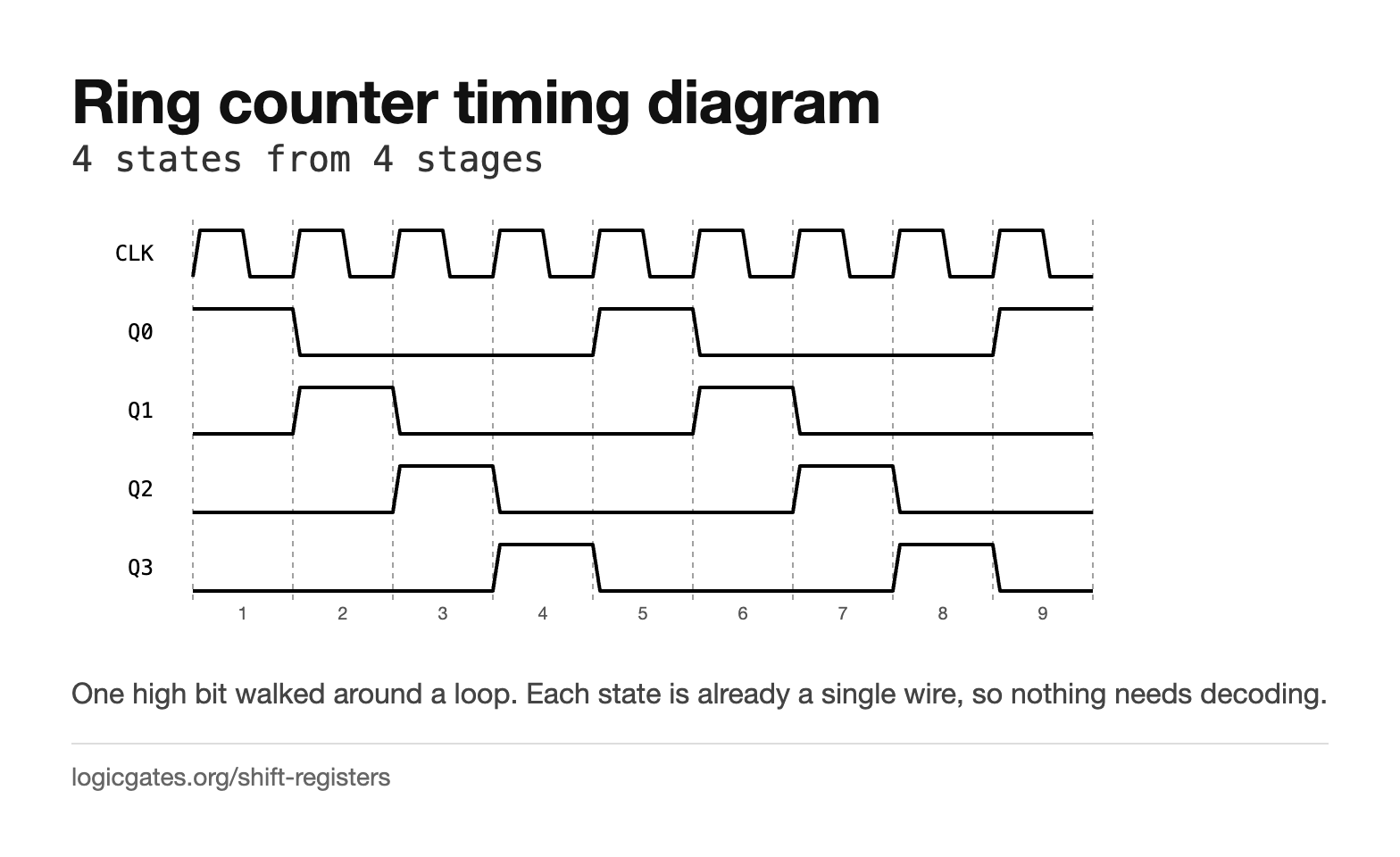 Click to download: Ring counter timing diagram
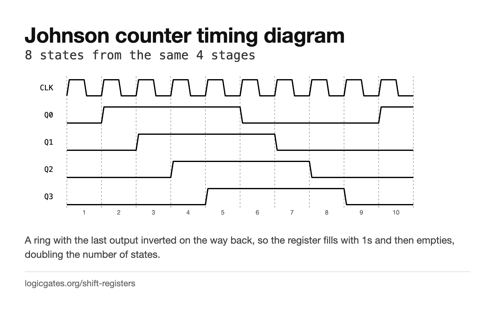 Click to download: Johnson counter timing diagram
Questions about shift registers
What is a shift register?
A row of flip-flops wired output to input, all sharing one clock. On every edge each stage takes whatever its neighbour was holding, so the whole contents move along by one place. Stage k holds what the input was k+1 cycles ago, and that is the entire behaviour.
What is a shift register used for?
Turning one wire into many and back. A serial in, parallel out register collects a byte arriving one bit at a time and presents all eight at once, which is what the receiving half of a UART does; a parallel in, serial out register does the reverse when sending. They are also delay lines, and with feedback they become counters or pseudo-random generators.
What is the difference between a ring counter and a Johnson counter?
A ring counter feeds the last stage straight back to the first, so a single high bit walks round and n stages give n states. A Johnson counter inverts on the way back, so the register fills with 1s and then empties, giving 2n states from the same hardware. A ring counter needs no decoding at all, because each state is already one wire; a Johnson counter is not one-hot, so it needs a gate per state, but only a two input one. Neither is self-correcting, so both have to be forced into a known state at reset.
How many flip-flops does a shift register need?
One per bit it holds. A four bit register is four flip-flops, and the data takes four clock edges to travel from the input to the last output. That delay is not a fault: it is what makes a shift register useful as a delay line and what sets how long a serial transfer takes.
Why is the output zero for the first few cycles?
Because the register starts empty and the data has not arrived yet. The last stage cannot show anything meaningful until the input has been clocked through every stage before it, so an n bit register has n cycles of latency. Real designs either clear the register first or ignore the output until it is full.