Flip-flops
A gate answers a question about right now. A flip-flop remembers. These four are the standard storage elements, and everything with state, from a counter to a processor register, is built from them.
The four of them
SR Q⁺ = S ∨ (¬R ∧ Q)
Set it, reset it, and it stays where you put it.
Read more →D Q⁺ = D
Whatever is on the input at the clock edge is what you get.
Read more →JK Q⁺ = (J ∧ ¬Q) ∨ (¬K ∧ Q)
Set, reset, hold, and the forbidden case turned into something useful.
Read more →T Q⁺ = T ⊻ Q
Hold when T is 0, invert when T is 1.
Read more →Which one to reach for
| Type | Inputs | Next state | Good for | Catch |
|---|---|---|---|---|
| SR | S, R | S ∨ (¬R ∧ Q) | Latching a condition until something clears it | S = R = 1 is not allowed |
| D | D | D | Registers, pipelines, holding a value steady | Cannot toggle without external logic |
| JK | J, K | (J ∧ ¬Q) ∨ (¬K ∧ Q) | State machines, counters, all four cases usable | Two inputs to drive instead of one |
| T | T | T ⊻ Q | Counters and clock division | Cannot load a specific value directly |
They are more alike than they look: each is an SR latch with different logic in front of it. Modern designs mostly use D, because a synthesis tool would rather build the extra logic than manage a second control input.
Latch or flip-flop?
The words are often used loosely, but the distinction matters once a circuit has a clock.
- A latch is level triggered. While its enable is high it is transparent: the output follows the input continuously. Turn the enable off and it holds whatever it had.
- A flip-flop is edge triggered. It only samples on the rising or falling edge of the clock, so its output changes at one predictable instant per clock period no matter what the input did in between.
That predictability is why synchronous designs use flip-flops throughout. Every stage captures its input at the same edge, so a signal has a whole clock period to settle before anything looks at it.
Start with two NOR gates wired into each other, which is the SR latch every other one is built on. The learning path walks through it.
Reference card
All four flip-flops with their equations and tables on one image.
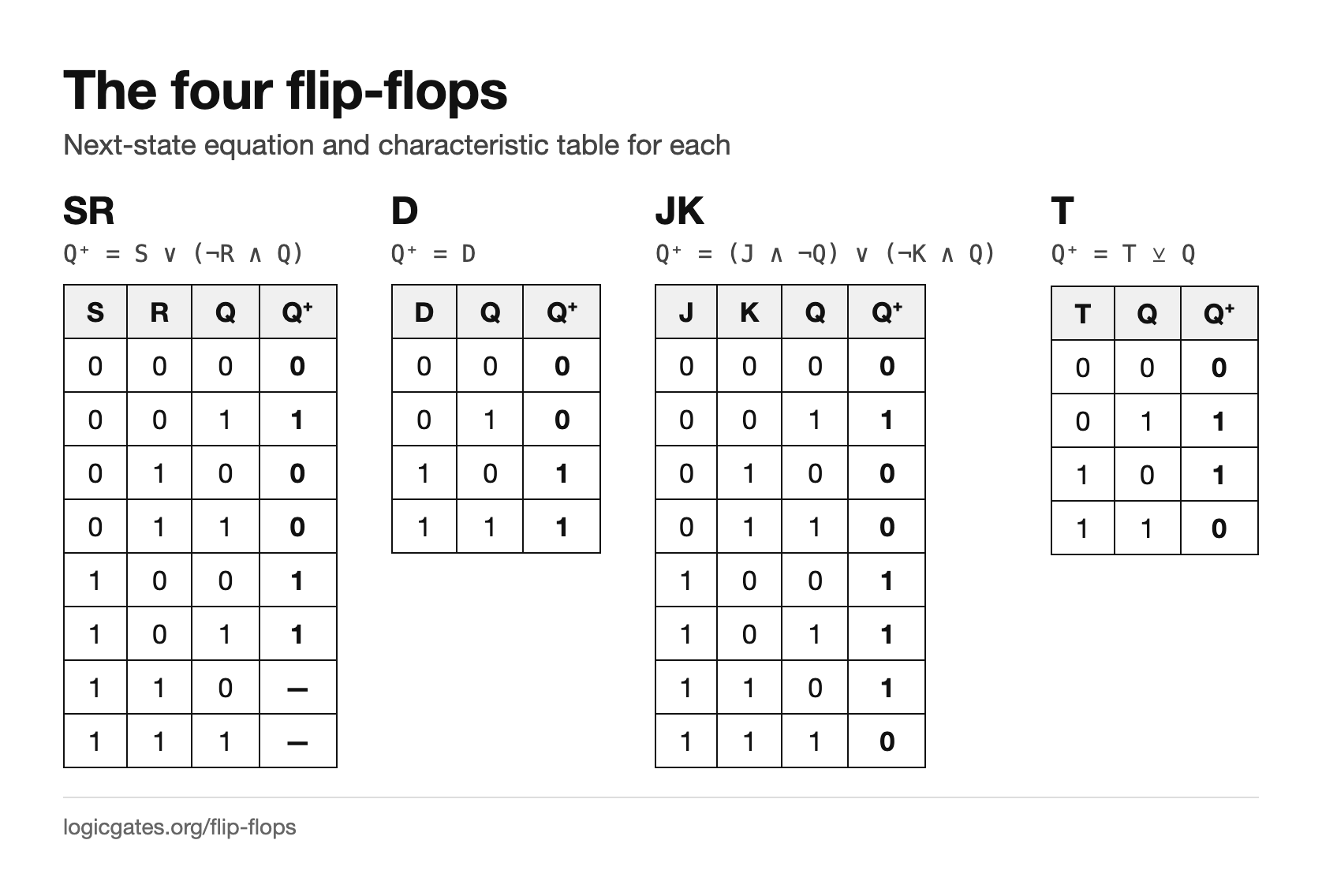 Click to download: Flip-flop comparison chart