D flip-flop
Whatever is on the input at the clock edge is what you get.
Live demo. Set the inputs, then clock it. Q⁺ = D
Nothing clocked yet. The state only moves on an edge.
How it behaves
The simplest useful flip-flop. On each active clock edge the output takes the value of D, and between edges it holds. There is no forbidden combination and nothing to remember: the next state is just the input.
D stands for data, or for delay, and both readings are fair. It captures a value and holds it steady for a whole clock period, which is exactly what you need to stop a signal changing while something else is trying to read it. Every register, every pipeline stage and most of the memory inside a processor is built from these.
Characteristic table
What the next state is, for every combination of inputs and present state. The equation below is this table written as algebra.
| D | Q | Q⁺ | Effect |
|---|---|---|---|
| 0 | 0 | 0 | load 0 |
| 0 | 1 | 0 | load 0 |
| 1 | 0 | 1 | load 1 |
| 1 | 1 | 1 | load 1 |
Q⁺ = D
Timing
The same behaviour in time rather than in a table. Each dashed line marks a clock cycle boundary — a rising edge, except for the last, which is just the end of the diagram — and Q only ever changes on an edge: that is what makes it a flip-flop rather than a latch. The inputs walk through every legal combination in turn, held for two cycles so you can see the response arrive a cycle late.
Reference card
The same waveform as an image, black on white, for notes or a slide.
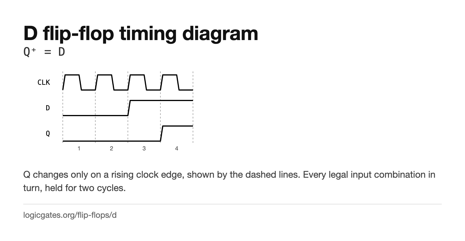 Click to download: D flip-flop timing diagram
Excitation table
The same information turned around. You know the transition you want; this says what to put on the inputs to get it. This is the table you use when designing a counter or a state machine, and the X's are what make the driving logic small.
| Q | Q⁺ | D |
|---|---|---|
| 0 | 0 | 0 |
| 0 | 1 | 1 |
| 1 | 0 | 0 |
| 1 | 1 | 1 |
An X means the input does not matter for that transition, which is a don't care when you minimise the logic that drives it.
Building one
An SR latch with S = D and R = ¬D, so the forbidden combination can never be reached. One common way to make it edge triggered is to chain two such latches on opposite clock phases, the master-slave arrangement; the classic 74LS74 uses a genuinely edge triggered circuit instead, which is not the same thing.
The editor has a Delay node, which is what you need to make feedback settle predictably rather than oscillating.
Where it is used
- Registers: one D flip-flop per bit, all sharing a clock, is how a processor holds a word.
- Pipeline stages, where each stage captures the previous one's result on the same edge.
- Synchronising an input that arrives at an unrelated time, usually two in a row to reduce the chance of metastability.
- Dividing a clock by two: feed the inverted output back into D and the output flips every edge.
Questions about the D flip-flop
What does the D stand for?
Data, and it is also read as delay, because the output follows the input one clock period later. Both descriptions fit what the circuit does.
What is the difference between a D latch and a D flip-flop?
A D latch is transparent while its enable is high: the output follows the input continuously. A D flip-flop only samples on the clock edge, so the output changes once per clock no matter how the input moves in between. Flip-flops are what synchronous designs use.