Common logic circuits
The handful of combinational blocks that everything else is assembled from. Each one is given as boolean expressions, with its complete truth table.
Half adder
Adds two bits. Two gates.
| A | B | sum | carry |
|---|---|---|---|
| 0 | 0 | 0 | 0 |
| 0 | 1 | 1 | 0 |
| 1 | 0 | 1 | 0 |
| 1 | 1 | 0 | 1 |
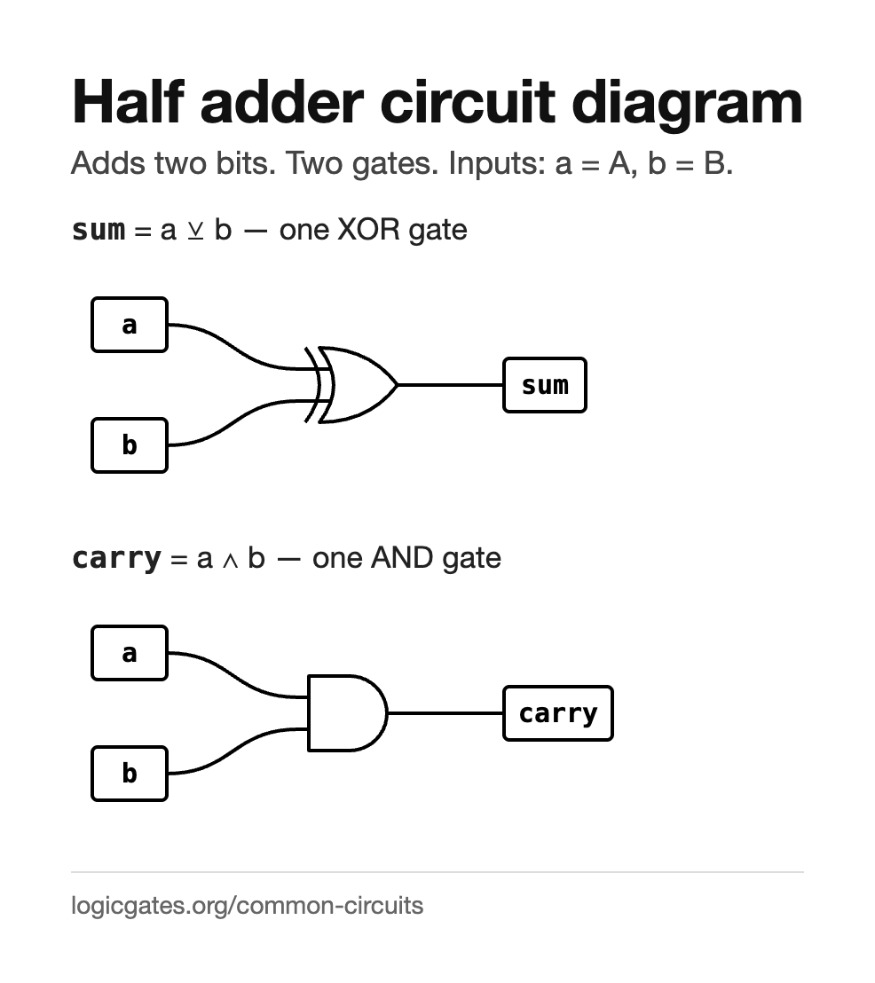
- sum
- a ^ b one XOR gate
- carry
- a & b one AND gate
Building it. Two toggles, an XOR and an AND fed from the same two inputs, and two displays. Package it as a custom node and the full adder becomes three parts.
Adding two single bits has four cases, and the two output columns turn out to be gates you already know. The sum is 1 when exactly one input is 1, which is XOR. The carry is 1 only when both are, which is AND. It is called a half adder because it has nowhere to accept a carry coming in from the column to its right.
- The least significant column of an adder, where there is no carry in.
- Incrementing a value by one, which is an adder with the second input tied to a constant.
- A first custom node to build, because everything larger is made of these.
Full adder
Adds two bits and a carry in.
| A | B | Cin | sum | cout |
|---|---|---|---|---|
| 0 | 0 | 0 | 0 | 0 |
| 0 | 0 | 1 | 1 | 0 |
| 0 | 1 | 0 | 1 | 0 |
| 0 | 1 | 1 | 0 | 1 |
| 1 | 0 | 0 | 1 | 0 |
| 1 | 0 | 1 | 0 | 1 |
| 1 | 1 | 0 | 0 | 1 |
| 1 | 1 | 1 | 1 | 1 |
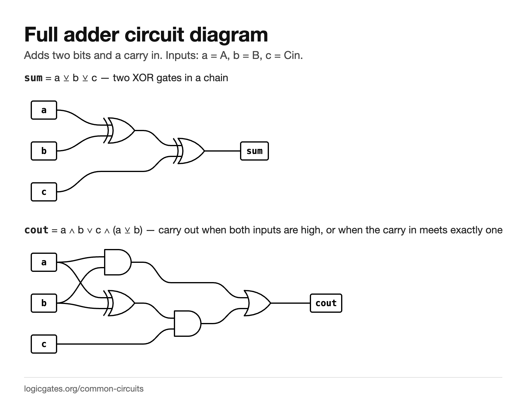
- sum
- a ^ b ^ c two XOR gates in a chain
- cout
- (a & b) | (c & (a ^ b)) carry out when both inputs are high, or when the carry in meets exactly one
Building it. Two half adders and an OR: the first adds a and b, the second adds that sum to the carry in, and the OR combines the two carries.
A third input lets the carry from the previous column join in, which is what makes the adder chainable. The sum is the XOR of all three inputs, and the carry out is high whenever at least two of the three are, so it is really a majority function wearing a different hat.
- Every column but the first of a ripple carry adder.
- Subtraction, by inverting one operand and setting the first carry in to 1.
- Counters and accumulators, which are adders with a register on the output.
2-to-1 multiplexer
Picks one of two inputs.
| A | B | S | out |
|---|---|---|---|
| 0 | 0 | 0 | 0 |
| 0 | 0 | 1 | 0 |
| 0 | 1 | 0 | 0 |
| 0 | 1 | 1 | 1 |
| 1 | 0 | 0 | 1 |
| 1 | 0 | 1 | 0 |
| 1 | 1 | 0 | 1 |
| 1 | 1 | 1 | 1 |
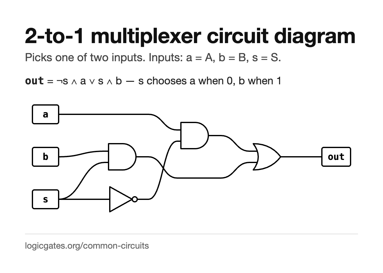
- out
- (!s & a) | (s & b) s chooses a when 0, b when 1
Building it. One NOT for the select, two ANDs and one OR. Watch the output follow whichever input the select points at.
A multiplexer is a switch made of gates. The select line enables one of two AND gates, and an OR merges them, so exactly one input reaches the output at a time. Widen the select to n bits and you can choose between 2^n inputs.
- Choosing between two data sources, which is how a processor picks an operand.
- Implementing any boolean function directly, by wiring the truth table into the data inputs.
- Sharing one bus between several senders, one at a time.
2-to-1 multiplexer: live diagram, reference card and questions →
1-to-2 demultiplexer
Sends one input to one of two outputs.
| D | S | y0 | y1 |
|---|---|---|---|
| 0 | 0 | 0 | 0 |
| 0 | 1 | 0 | 0 |
| 1 | 0 | 1 | 0 |
| 1 | 1 | 0 | 1 |
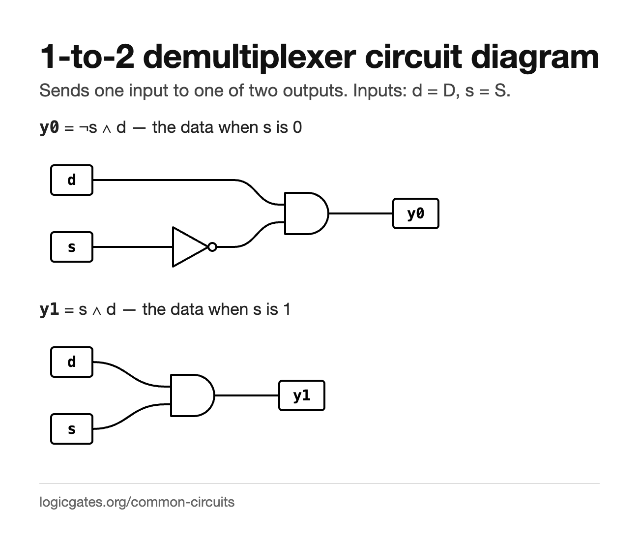
- y0
- !s & d the data when s is 0
- y1
- s & d the data when s is 1
Building it. One NOT and two ANDs. It is a decoder with the data line ANDed into every output.
The mirror image of a multiplexer. One data line goes in, the select decides which output it comes out of, and the other output stays low. Chain them and one signal can be routed to any of many destinations.
- Routing a signal to one of several destinations, such as picking a memory bank.
- Turning a binary address into an enable line for the addressed device.
- Serial to parallel conversion, together with some storage.
1-to-2 demultiplexer: live diagram, reference card and questions →
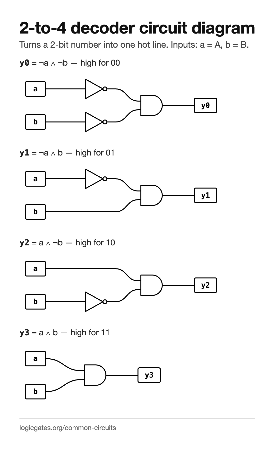
2-to-4 decoder
Turns a 2-bit number into one hot line.
| A | B | y0 | y1 | y2 | y3 |
|---|---|---|---|---|---|
| 0 | 0 | 1 | 0 | 0 | 0 |
| 0 | 1 | 0 | 1 | 0 | 0 |
| 1 | 0 | 0 | 0 | 1 | 0 |
| 1 | 1 | 0 | 0 | 0 | 1 |
- y0
- !a & !b high for 00
- y1
- !a & b high for 01
- y2
- a & !b high for 10
- y3
- a & b high for 11
Building it. Two NOTs and four ANDs. Toggle the inputs and watch exactly one output light at a time.
A decoder raises exactly one output, the one whose number matches the input. Each output is a single AND of the inputs in the right polarities, which means a decoder is really all the minterms of its inputs made available at once.
- Address decoding: picking which chip or register a bus address refers to.
- Driving a display, where each output lights one element.
- Building any function at all, by ORing together the minterms you want.
2-to-4 decoder: live diagram, reference card and questions →
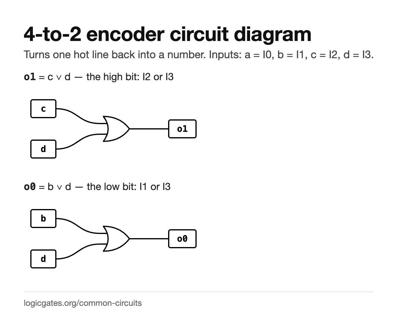
4-to-2 encoder
Turns one hot line back into a number.
| I0 | I1 | I2 | I3 | o1 | o0 |
|---|---|---|---|---|---|
| 0 | 0 | 0 | 0 | 0 | 0 |
| 0 | 0 | 0 | 1 | 1 | 1 |
| 0 | 0 | 1 | 0 | 1 | 0 |
| 0 | 0 | 1 | 1 | 1 | 1 |
| 0 | 1 | 0 | 0 | 0 | 1 |
| 0 | 1 | 0 | 1 | 1 | 1 |
| 0 | 1 | 1 | 0 | 1 | 1 |
| 0 | 1 | 1 | 1 | 1 | 1 |
| 1 | 0 | 0 | 0 | 0 | 0 |
| 1 | 0 | 0 | 1 | 1 | 1 |
| 1 | 0 | 1 | 0 | 1 | 0 |
| 1 | 0 | 1 | 1 | 1 | 1 |
| 1 | 1 | 0 | 0 | 0 | 1 |
| 1 | 1 | 0 | 1 | 1 | 1 |
| 1 | 1 | 1 | 0 | 1 | 1 |
| 1 | 1 | 1 | 1 | 1 | 1 |
- o1
- c | d the high bit: I2 or I3
- o0
- b | d the low bit: I1 or I3
Building it. Two OR gates is the whole circuit. Making it a priority encoder, so that a higher line wins when two are high, needs one more NOT and AND here: o0 becomes I3 or (I1 and not I2).
The reverse of a decoder: four lines in, a two bit number out saying which one is high. It assumes exactly one input is active. If two are, the output is the OR of their codes rather than either of them, which is why real designs use a priority encoder that picks the highest instead. Note also that all zeros and I0 alone both give 00, so a real encoder adds a valid output to tell them apart.
- Reading a keypad, where one key is down at a time.
- Interrupt handling, usually as a priority encoder so simultaneous requests resolve.
- Compressing a one hot state register back into a binary state number.
4-to-2 encoder: live diagram, reference card and questions →
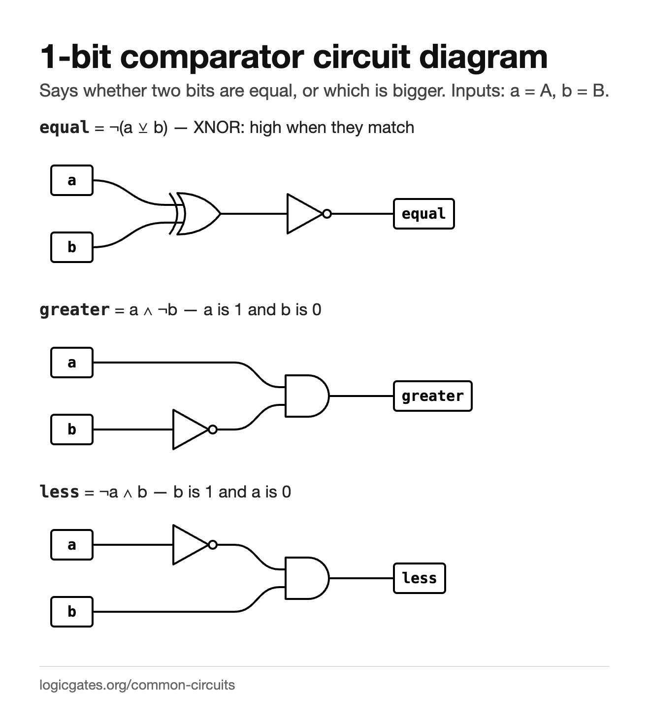
1-bit comparator
Says whether two bits are equal, or which is bigger.
| A | B | equal | greater | less |
|---|---|---|---|---|
| 0 | 0 | 1 | 0 | 0 |
| 0 | 1 | 0 | 0 | 1 |
| 1 | 0 | 0 | 1 | 0 |
| 1 | 1 | 1 | 0 | 0 |
- equal
- !(a ^ b) XNOR: high when they match
- greater
- a & !b a is 1 and b is 0
- less
- !a & b b is 1 and a is 0
Building it. An XOR with a NOT for equality, and two ANDs with a NOT each for the other two. Check that exactly one output is ever high.
Comparing one bit needs three answers, and exactly one of them is true at any time. Equality is just XOR inverted, since XOR asks whether the inputs differ. Widening it to several bits means comparing from the most significant end and only looking further down when the bits so far are equal.
- Testing two values for equality, which a processor does on every branch.
- Sorting networks and min or max circuits.
- Detecting that a counter has reached a target value.
1-bit comparator: live diagram, reference card and questions →
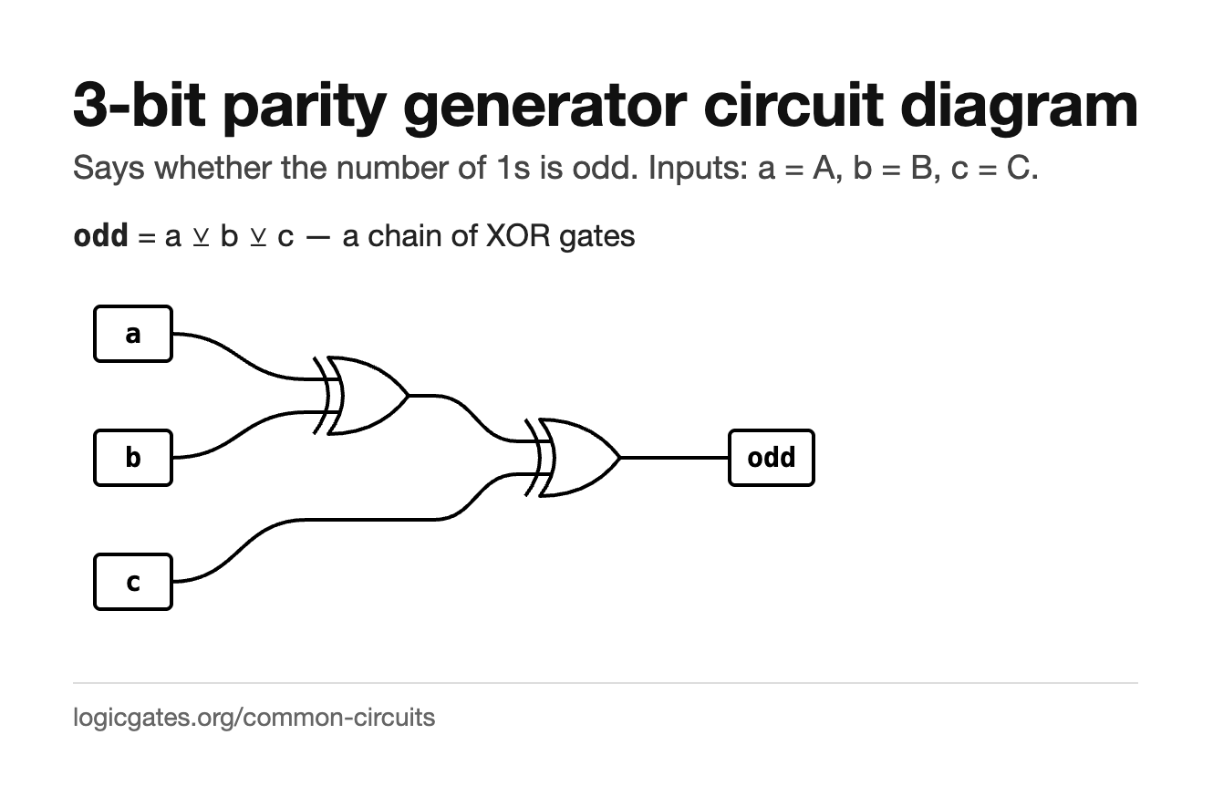
3-bit parity generator
Says whether the number of 1s is odd.
| A | B | C | odd |
|---|---|---|---|
| 0 | 0 | 0 | 0 |
| 0 | 0 | 1 | 1 |
| 0 | 1 | 0 | 1 |
| 0 | 1 | 1 | 0 |
| 1 | 0 | 0 | 1 |
| 1 | 0 | 1 | 0 |
| 1 | 1 | 0 | 0 |
| 1 | 1 | 1 | 1 |
- odd
- a ^ b ^ c a chain of XOR gates
Building it. Two XOR gates in a chain, which is the even parity bit. Adding a NOT on the end gives odd parity instead.
XOR gates chained together answer one question: is the number of high inputs odd? Send that bit along with the data and the receiver can recompute it. If the two disagree, something flipped on the way, which catches any single bit error.
- Error detection on serial links and older memory buses.
- The starting point for a CRC, which is the same idea run over many bits at once.
- The sum output of an adder, which is the parity of its three inputs.
3-bit parity generator: live diagram, reference card and questions →
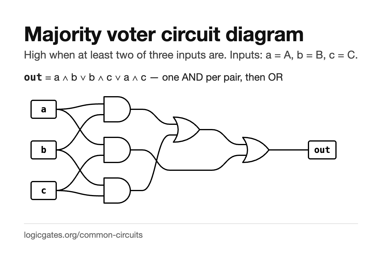
Majority voter
High when at least two of three inputs are.
| A | B | C | out |
|---|---|---|---|
| 0 | 0 | 0 | 0 |
| 0 | 0 | 1 | 0 |
| 0 | 1 | 0 | 0 |
| 0 | 1 | 1 | 1 |
| 1 | 0 | 0 | 0 |
| 1 | 0 | 1 | 1 |
| 1 | 1 | 0 | 1 |
| 1 | 1 | 1 | 1 |
- out
- (a & b) | (b & c) | (a & c) one AND per pair, then OR
Building it. Three ANDs and one OR. It cannot be made smaller as a sum of products, which the Karnaugh map solver will confirm.
Three inputs vote and the majority wins. It is the same function as the carry out of a full adder, which is worth noticing: adding three bits produces a carry exactly when at least two of them are 1.
- Redundant systems, where three copies of a circuit vote so one failure is outvoted.
- The carry path of an adder.
- Smoothing a noisy signal by voting over three samples.
Majority voter: live diagram, reference card and questions →
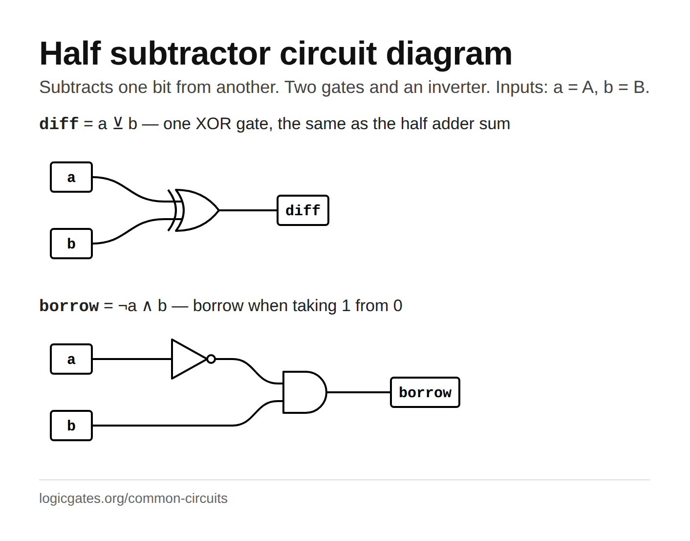
Half subtractor
Subtracts one bit from another. Two gates and an inverter.
| A | B | diff | borrow |
|---|---|---|---|
| 0 | 0 | 0 | 0 |
| 0 | 1 | 1 | 1 |
| 1 | 0 | 1 | 0 |
| 1 | 1 | 0 | 0 |
- diff
- a ^ b one XOR gate, the same as the half adder sum
- borrow
- !a & b borrow when taking 1 from 0
Building it. Two toggles, an XOR for the difference, and a NOT into an AND for the borrow. Compare it to the half adder: only the NOT is new.
Subtracting B from A one bit at a time has the same four cases as adding, and the difference column is the same XOR. What changes is the carry: subtraction borrows, and only one case needs it, 0 minus 1. So the borrow is 1 exactly when A is 0 and B is 1, which is ¬A ∧ B rather than the adder's A ∧ B.
- The least significant column of a subtractor, where nothing has been borrowed yet.
- The rightmost column of a decrementer, which is a chain of these with a constant 1 fed into that column.
- Showing why adders and subtractors are the same circuit apart from one inverted input.
Half subtractor: live diagram, reference card and questions →
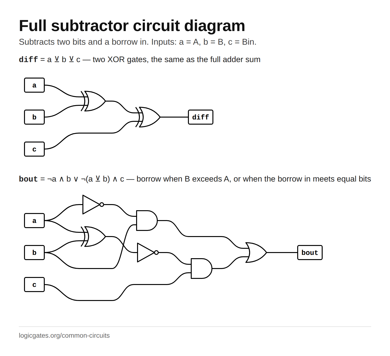
Full subtractor
Subtracts two bits and a borrow in.
| A | B | Bin | diff | bout |
|---|---|---|---|---|
| 0 | 0 | 0 | 0 | 0 |
| 0 | 0 | 1 | 1 | 1 |
| 0 | 1 | 0 | 1 | 1 |
| 0 | 1 | 1 | 0 | 1 |
| 1 | 0 | 0 | 1 | 0 |
| 1 | 0 | 1 | 0 | 0 |
| 1 | 1 | 0 | 0 | 0 |
| 1 | 1 | 1 | 1 | 1 |
- diff
- a ^ b ^ c two XOR gates, the same as the full adder sum
- bout
- (!a & b) | (!(a ^ b) & c) borrow when B exceeds A, or when the borrow in meets equal bits
Building it. Two half subtractors and an OR, mirroring the full adder: the first takes B from A, the second subtracts the borrow in from that difference, and the OR combines the two borrows.
A third input takes the borrow from the column to the right, which is what makes the subtractor chainable. The difference is the XOR of all three inputs, exactly as in the full adder. The borrow out is 1 when B alone exceeds A, or when A and B are equal and the incoming borrow has to be passed on: ¬A ∧ B ∨ ¬(A ⊕ B) ∧ Bin.
- Every column but the first of a ripple borrow subtractor.
- Comparing two numbers, since a subtraction that ends with a borrow out means the second number was bigger.
- The subtract half of an arithmetic unit, though most real designs add the two's complement instead and reuse the adder.
Full subtractor: live diagram, reference card and questions →
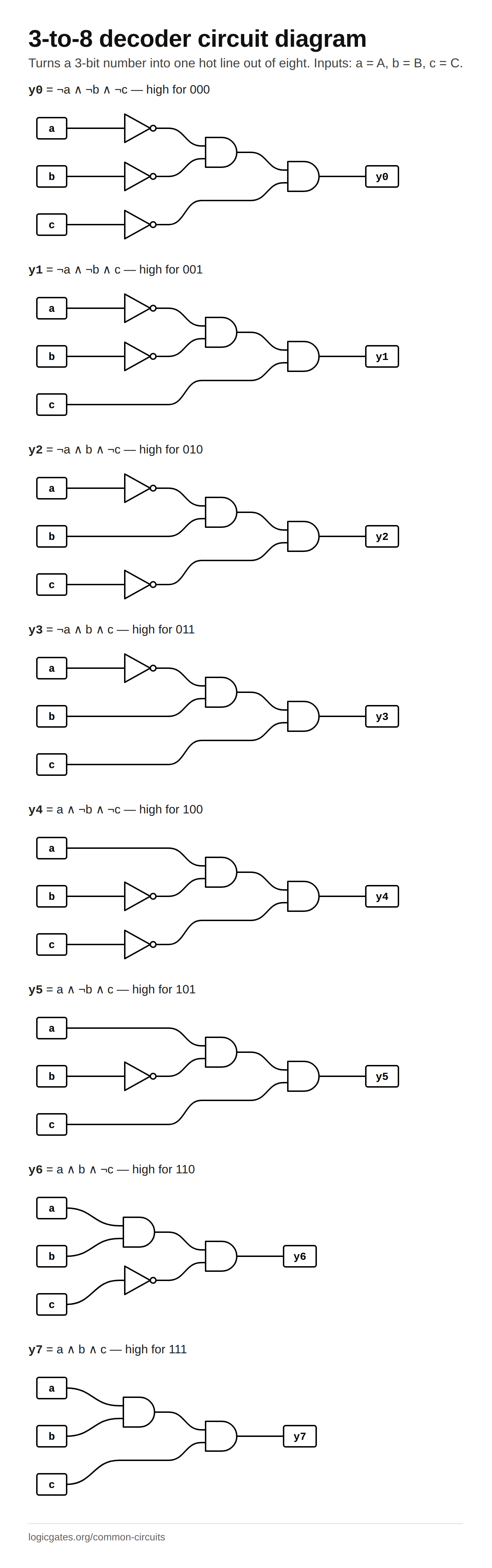
3-to-8 decoder
Turns a 3-bit number into one hot line out of eight.
| A | B | C | y0 | y1 | y2 | y3 | y4 | y5 | y6 | y7 |
|---|---|---|---|---|---|---|---|---|---|---|
| 0 | 0 | 0 | 1 | 0 | 0 | 0 | 0 | 0 | 0 | 0 |
| 0 | 0 | 1 | 0 | 1 | 0 | 0 | 0 | 0 | 0 | 0 |
| 0 | 1 | 0 | 0 | 0 | 1 | 0 | 0 | 0 | 0 | 0 |
| 0 | 1 | 1 | 0 | 0 | 0 | 1 | 0 | 0 | 0 | 0 |
| 1 | 0 | 0 | 0 | 0 | 0 | 0 | 1 | 0 | 0 | 0 |
| 1 | 0 | 1 | 0 | 0 | 0 | 0 | 0 | 1 | 0 | 0 |
| 1 | 1 | 0 | 0 | 0 | 0 | 0 | 0 | 0 | 1 | 0 |
| 1 | 1 | 1 | 0 | 0 | 0 | 0 | 0 | 0 | 0 | 1 |
- y0
- !a & !b & !c high for 000
- y1
- !a & !b & c high for 001
- y2
- !a & b & !c high for 010
- y3
- !a & b & c high for 011
- y4
- a & !b & !c high for 100
- y5
- a & !b & c high for 101
- y6
- a & b & !c high for 110
- y7
- a & b & c high for 111
Building it. Three NOTs and eight ANDs with three inputs each; the simulator lets an AND take three inputs directly. Wire the inputs to three toggles and watch one output at a time light as you count.
The same idea as the 2-to-4 decoder with one more input bit: each output is a single three-input AND of the inputs in the right polarity, so the eight outputs are the eight minterms of A, B and C. Three inverters and eight AND gates make the whole circuit, and this is the size that turns up most often as a real part, the 74138, which adds enable inputs so that two of them can be wired into a 4-to-16.
- Selecting one of eight registers, memory chips or peripherals from three address bits.
- Generating all the minterms of three variables at once, so any three-input function is an OR of some outputs.
- Converting a three bit state number into one hot signals for a state machine.
3-to-8 decoder: live diagram, reference card and questions →
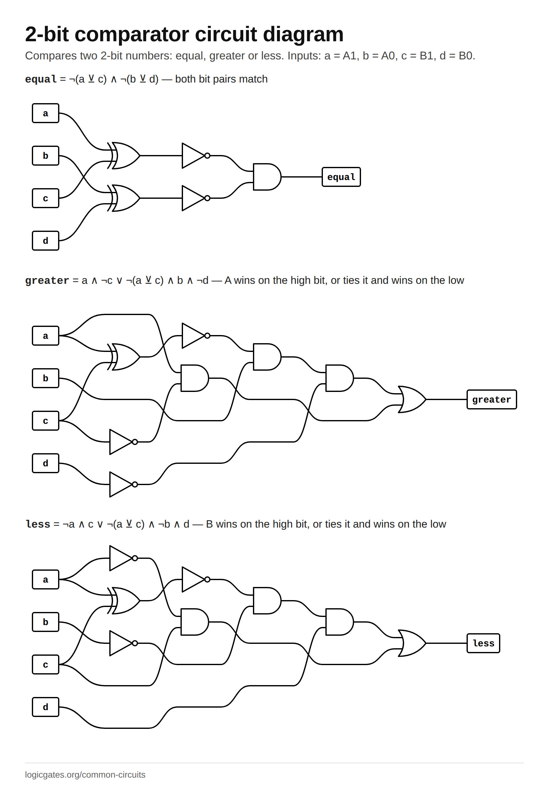
2-bit comparator
Compares two 2-bit numbers: equal, greater or less.
| A1 | A0 | B1 | B0 | equal | greater | less |
|---|---|---|---|---|---|---|
| 0 | 0 | 0 | 0 | 1 | 0 | 0 |
| 0 | 0 | 0 | 1 | 0 | 0 | 1 |
| 0 | 0 | 1 | 0 | 0 | 0 | 1 |
| 0 | 0 | 1 | 1 | 0 | 0 | 1 |
| 0 | 1 | 0 | 0 | 0 | 1 | 0 |
| 0 | 1 | 0 | 1 | 1 | 0 | 0 |
| 0 | 1 | 1 | 0 | 0 | 0 | 1 |
| 0 | 1 | 1 | 1 | 0 | 0 | 1 |
| 1 | 0 | 0 | 0 | 0 | 1 | 0 |
| 1 | 0 | 0 | 1 | 0 | 1 | 0 |
| 1 | 0 | 1 | 0 | 1 | 0 | 0 |
| 1 | 0 | 1 | 1 | 0 | 0 | 1 |
| 1 | 1 | 0 | 0 | 0 | 1 | 0 |
| 1 | 1 | 0 | 1 | 0 | 1 | 0 |
| 1 | 1 | 1 | 0 | 0 | 1 | 0 |
| 1 | 1 | 1 | 1 | 1 | 0 | 0 |
- equal
- !(a ^ c) & !(b ^ d) both bit pairs match
- greater
- (a & !c) | (!(a ^ c) & b & !d) A wins on the high bit, or ties it and wins on the low
- less
- (!a & c) | (!(a ^ c) & !b & d) B wins on the high bit, or ties it and wins on the low
Building it. Two XNORs for the per-bit equality, then an AND for equal and two AND-OR networks for greater and less. Check that exactly one of the three outputs is high for every one of the sixteen input combinations.
Comparing two bits at a time is the 1-bit comparator twice, with a rule for combining them: the high bits decide unless they are equal, in which case the low bits decide. Equality is the AND of the two per-bit XNORs. Greater is "A1 beats B1" or "the high bits tie and A0 beats B0", and less is the mirror image. Widening to more bits adds one more term per bit, each guarded by every tie above it.
- Branch decisions on small fields such as priority levels or opcodes.
- Detecting that a 2-bit counter has passed a threshold.
- The building block of wider comparators, which chain these so that a lower stage only decides when every stage above it reports equal.
2-bit comparator: live diagram, reference card and questions →
Putting them together
None of these is interesting alone. What makes them worth knowing is that they compose, and the simulator lets you package each one into a node you can reuse.
- Two half adders and an OR make a full adder.
- Four full adders in a row make a four bit ripple carry adder, each carry feeding the next.
- An adder with one input inverted and the first carry set to 1 becomes a subtractor, because that is two's complement.
- A decoder plus a set of ORs builds any function at all, straight from its truth table.
- Four input bits and seven output functions make a seven-segment decoder, the classic exercise in using don't cares.
- Add a flip-flop and an adder becomes a counter, which is where combinational logic stops and sequential logic starts.
Or draw any of the expressions above with the circuit diagram generator. The adders are also where two's complement earns its keep: feed one input its complement and the same circuit subtracts.
Reference cards
Every circuit above as a gate diagram, black on white, for notes or a slide.
 Click to download: Half adder circuit diagram
 Click to download: Full adder circuit diagram
 Click to download: 2-to-1 multiplexer circuit diagram
 Click to download: 1-to-2 demultiplexer circuit diagram
 Click to download: 2-to-4 decoder circuit diagram
 Click to download: 4-to-2 encoder circuit diagram
 Click to download: 1-bit comparator circuit diagram
 Click to download: 3-bit parity generator circuit diagram
 Click to download: Majority voter circuit diagram
 Click to download: Half subtractor circuit diagram
 Click to download: Full subtractor circuit diagram
 Click to download: 3-to-8 decoder circuit diagram
 Click to download: 2-bit comparator circuit diagram
Questions
What is the difference between a half adder and a full adder?
A half adder adds two bits and produces a sum and a carry, but has no way to accept a carry coming in. A full adder takes a third input for that carry, which is what lets adders be chained one per bit. The first column of an adder can be a half adder; every column after it must be a full adder.
What is the difference between a multiplexer and a decoder?
A multiplexer has many data inputs and one output, and the select lines choose which input reaches it. A decoder has only the select lines and raises exactly one of its many outputs. A demultiplexer is the mux run backwards: one input, many outputs, and it is a decoder with the data line ANDed into each output.
Are these circuits combinational?
Yes, all of them. Every output depends only on the inputs at that moment, with no feedback and no memory, which is why each one can be written as a boolean expression and printed as a complete truth table. Anything that has to remember needs a flip-flop instead.
How do I build these in the simulator?
Place the gates from the Logic menu, wire them up, then use File then Create node to package the result. Once a half adder is a custom node, a full adder is two of them and an OR gate, and a four bit adder is four full adders in a row.