3-bit parity generator
A parity generator is a combinational circuit that reports whether the number of 1s among its inputs is odd, using a chain of XOR gates, so that one extra bit can be sent alongside data to catch a single flipped bit.
Says whether the number of 1s is odd.
Circuit diagram
Toggle the inputs and follow the signals: green wires are high, red are low. The highlighted row of the truth table below is the one you have set.
Truth table
| A | B | C | odd |
|---|---|---|---|
| 0 | 0 | 0 | 0 |
| 0 | 0 | 1 | 1 |
| 0 | 1 | 0 | 1 |
| 0 | 1 | 1 | 0 |
| 1 | 0 | 0 | 1 |
| 1 | 0 | 1 | 0 |
| 1 | 1 | 0 | 0 |
| 1 | 1 | 1 | 1 |
Boolean expressions
- odd
- a ⊻ b ⊻ c a chain of XOR gates
How it works
XOR gates chained together answer one question: is the number of high inputs odd? Send that bit along with the data and the receiver can recompute it. If the two disagree, something flipped on the way, which catches any single bit error.
Where it is used
- Error detection on serial links and older memory buses.
- The starting point for a CRC, which is the same idea run over many bits at once.
- The sum output of an adder, which is the parity of its three inputs.
Build it
Two XOR gates in a chain, which is the even parity bit. Adding a NOT on the end gives odd parity instead.
Or draw it from the expressions above with the circuit diagram generator, in either symbol standard, and export it as SVG, PNG, Verilog or VHDL.
Reference card
The diagram above as an image, black on white, for notes or a slide.
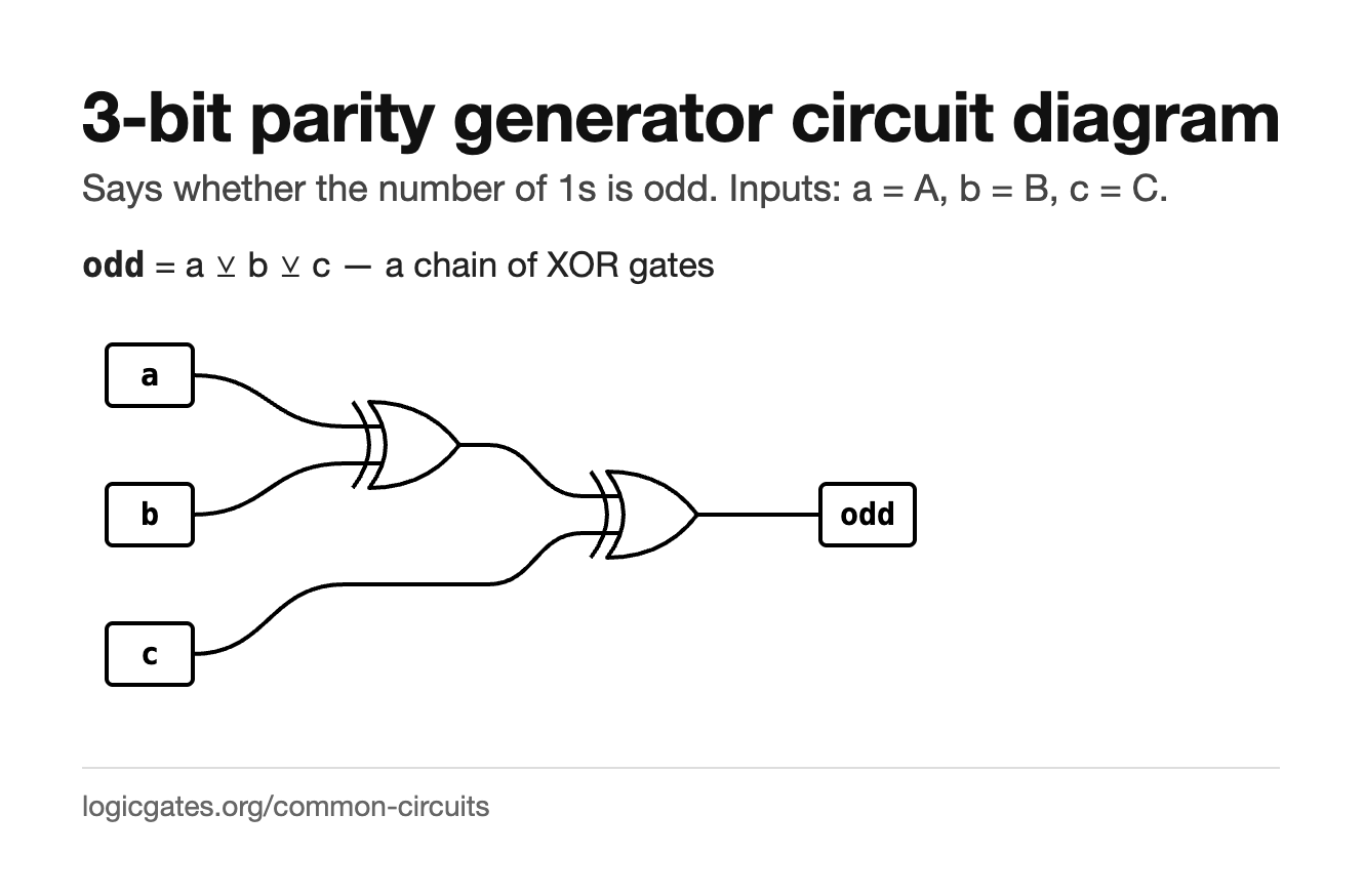 Click to download: 3-bit parity generator circuit diagram
Questions about the 3-bit parity generator
What is the difference between odd and even parity?
With even parity the parity bit is chosen so the total number of 1s, data plus parity bit, is even; with odd parity so the total is odd. The generator is the same XOR chain either way, with a NOT on the end for odd. The receiver recomputes and compares, and a mismatch means a bit flipped in transit.
How many errors can a parity bit catch?
Any odd number of flipped bits, which in practice means the single bit error that is by far the most common. Two flipped bits cancel out and go unnoticed. Catching more, or finding out which bit flipped, needs a longer code such as a Hamming code or a CRC, both of which are built from the same XOR idea run over more bits.
Why is parity the same as an adder's sum output?
Because the sum bit of a full adder is A ⊕ B ⊕ Cin, and that is 1 exactly when an odd number of the three inputs are 1. A parity generator and the sum path of an adder are the same circuit asked a different question.