Full subtractor
A full subtractor is a combinational circuit that subtracts a bit and an incoming borrow from another bit, producing a difference bit and a borrow out, so that copies of it can be chained one per column to subtract whole numbers.
Subtracts two bits and a borrow in.
Circuit diagram
Toggle the inputs and follow the signals: green wires are high, red are low. The highlighted row of the truth table below is the one you have set.
Truth table
| A | B | Bin | diff | bout |
|---|---|---|---|---|
| 0 | 0 | 0 | 0 | 0 |
| 0 | 0 | 1 | 1 | 1 |
| 0 | 1 | 0 | 1 | 1 |
| 0 | 1 | 1 | 0 | 1 |
| 1 | 0 | 0 | 1 | 0 |
| 1 | 0 | 1 | 0 | 0 |
| 1 | 1 | 0 | 0 | 0 |
| 1 | 1 | 1 | 1 | 1 |
Boolean expressions
- diff
- a ⊻ b ⊻ c two XOR gates, the same as the full adder sum
- bout
- ¬a ∧ b ∨ ¬(a ⊻ b) ∧ c borrow when B exceeds A, or when the borrow in meets equal bits
How it works
A third input takes the borrow from the column to the right, which is what makes the subtractor chainable. The difference is the XOR of all three inputs, exactly as in the full adder. The borrow out is 1 when B alone exceeds A, or when A and B are equal and the incoming borrow has to be passed on: ¬A ∧ B ∨ ¬(A ⊕ B) ∧ Bin.
Where it is used
- Every column but the first of a ripple borrow subtractor.
- Comparing two numbers, since a subtraction that ends with a borrow out means the second number was bigger.
- The subtract half of an arithmetic unit, though most real designs add the two's complement instead and reuse the adder.
Build it
Two half subtractors and an OR, mirroring the full adder: the first takes B from A, the second subtracts the borrow in from that difference, and the OR combines the two borrows.
Or draw it from the expressions above with the circuit diagram generator, in either symbol standard, and export it as SVG, PNG, Verilog or VHDL.
Reference card
The diagram above as an image, black on white, for notes or a slide.
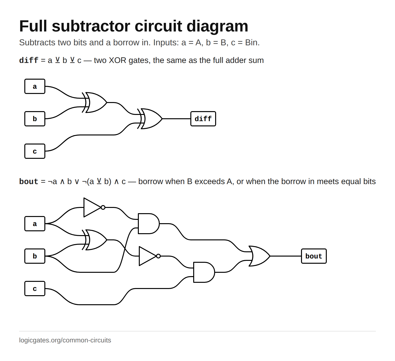 Click to download: Full subtractor circuit diagram
Questions about the full subtractor
What is the truth table of a full subtractor?
Eight rows, one per combination of A, B and the borrow in. The difference is 1 whenever an odd number of the three inputs are 1, which is their XOR. The borrow out is 1 when B is 1 and A is 0, and also when A equals B and the borrow in is 1: in both cases the column has to borrow from the next one.
What is the difference between a full adder and a full subtractor?
The sum and difference are the same XOR of three inputs. The carry out of an adder is 1 when at least two inputs are 1; the borrow out of a subtractor is 1 when B and the borrow in together outweigh A. Invert A in the adder's carry equation and you get the borrow equation. A practical adder-subtractor takes a different route, inverting B and setting the carry in to 1, which the next question explains.
Why do processors not use subtractors?
Because A minus B equals A plus the two's complement of B, and the two's complement is just every bit of B inverted with 1 added, which an adder can do by setting its first carry in to 1. One adder with an XOR on each B input therefore adds and subtracts, so a separate subtractor circuit is rarely built.