3-to-8 decoder
A 3-to-8 decoder is a combinational circuit that takes a three-bit binary number and raises exactly one of its eight outputs, the one whose index matches the input.
Turns a 3-bit number into one hot line out of eight.
Circuit diagram
Toggle the inputs and follow the signals: green wires are high, red are low. The highlighted row of the truth table below is the one you have set.
Truth table
| A | B | C | y0 | y1 | y2 | y3 | y4 | y5 | y6 | y7 |
|---|---|---|---|---|---|---|---|---|---|---|
| 0 | 0 | 0 | 1 | 0 | 0 | 0 | 0 | 0 | 0 | 0 |
| 0 | 0 | 1 | 0 | 1 | 0 | 0 | 0 | 0 | 0 | 0 |
| 0 | 1 | 0 | 0 | 0 | 1 | 0 | 0 | 0 | 0 | 0 |
| 0 | 1 | 1 | 0 | 0 | 0 | 1 | 0 | 0 | 0 | 0 |
| 1 | 0 | 0 | 0 | 0 | 0 | 0 | 1 | 0 | 0 | 0 |
| 1 | 0 | 1 | 0 | 0 | 0 | 0 | 0 | 1 | 0 | 0 |
| 1 | 1 | 0 | 0 | 0 | 0 | 0 | 0 | 0 | 1 | 0 |
| 1 | 1 | 1 | 0 | 0 | 0 | 0 | 0 | 0 | 0 | 1 |
Boolean expressions
- y0
- ¬a ∧ ¬b ∧ ¬c high for 000
- y1
- ¬a ∧ ¬b ∧ c high for 001
- y2
- ¬a ∧ b ∧ ¬c high for 010
- y3
- ¬a ∧ b ∧ c high for 011
- y4
- a ∧ ¬b ∧ ¬c high for 100
- y5
- a ∧ ¬b ∧ c high for 101
- y6
- a ∧ b ∧ ¬c high for 110
- y7
- a ∧ b ∧ c high for 111
How it works
The same idea as the 2-to-4 decoder with one more input bit: each output is a single three-input AND of the inputs in the right polarity, so the eight outputs are the eight minterms of A, B and C. Three inverters and eight AND gates make the whole circuit, and this is the size that turns up most often as a real part, the 74138, which adds enable inputs so that two of them can be wired into a 4-to-16.
Where it is used
- Selecting one of eight registers, memory chips or peripherals from three address bits.
- Generating all the minterms of three variables at once, so any three-input function is an OR of some outputs.
- Converting a three bit state number into one hot signals for a state machine.
Build it
Three NOTs and eight ANDs with three inputs each; the simulator lets an AND take three inputs directly. Wire the inputs to three toggles and watch one output at a time light as you count.
Or draw it from the expressions above with the circuit diagram generator, in either symbol standard, and export it as SVG, PNG, Verilog or VHDL.
Reference card
The diagram above as an image, black on white, for notes or a slide.
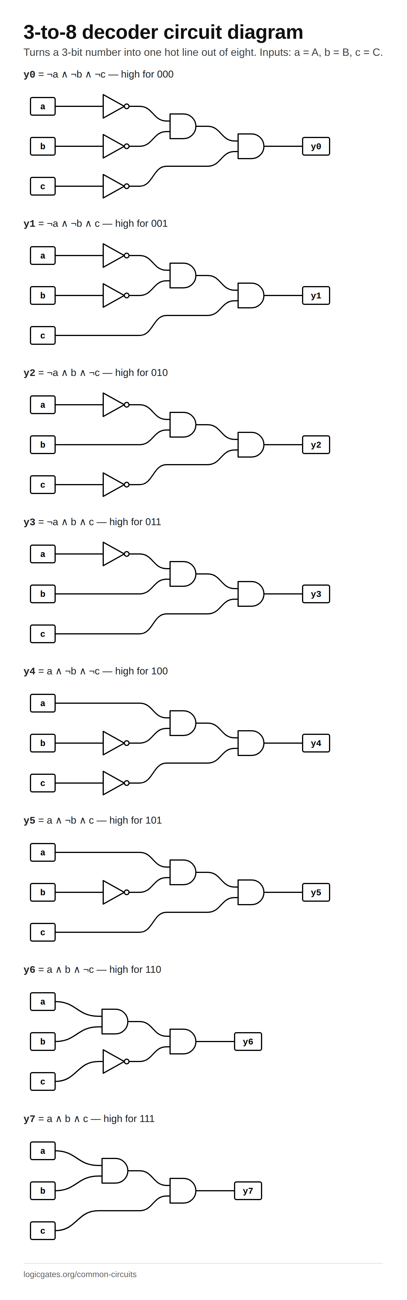 Click to download: 3-to-8 decoder circuit diagram
Questions about the 3-to-8 decoder
How does a 3-to-8 decoder work?
Each output is an AND gate that is only satisfied by one input pattern. Y5, for instance, is A ∧ ¬B ∧ C, which is 1 only for 101. Three inverters supply the complemented inputs, so the whole circuit is three NOT gates and eight three-input AND gates, and exactly one output is high at any time.
How do you make a 4-to-16 decoder from 3-to-8 decoders?
Use two of them and the fourth, most significant, input bit as an enable: when it is 1 it enables the upper decoder, for outputs 8 to 15, and inverted it enables the lower one. Real 3-to-8 parts such as the 74138 have an active-high enable and two active-low ones, so with them no inverter is needed, and the same trick stacks any number of stages.
What is the difference between a decoder and a demultiplexer?
A demultiplexer is a decoder with a data input ANDed into every output, so the selected line carries the data rather than a constant 1. A decoder with an enable input is already a demultiplexer if you feed the data into the enable, which is why parts like the 74138 are sold under both names.