2-bit comparator
A 2-bit magnitude comparator is a combinational circuit that takes two two-bit numbers and reports whether the first is equal to, greater than or less than the second, by comparing the high bits first and the low bits only when the high bits match.
Compares two 2-bit numbers: equal, greater or less.
Circuit diagram
Toggle the inputs and follow the signals: green wires are high, red are low. The highlighted row of the truth table below is the one you have set.
Truth table
| A1 | A0 | B1 | B0 | equal | greater | less |
|---|---|---|---|---|---|---|
| 0 | 0 | 0 | 0 | 1 | 0 | 0 |
| 0 | 0 | 0 | 1 | 0 | 0 | 1 |
| 0 | 0 | 1 | 0 | 0 | 0 | 1 |
| 0 | 0 | 1 | 1 | 0 | 0 | 1 |
| 0 | 1 | 0 | 0 | 0 | 1 | 0 |
| 0 | 1 | 0 | 1 | 1 | 0 | 0 |
| 0 | 1 | 1 | 0 | 0 | 0 | 1 |
| 0 | 1 | 1 | 1 | 0 | 0 | 1 |
| 1 | 0 | 0 | 0 | 0 | 1 | 0 |
| 1 | 0 | 0 | 1 | 0 | 1 | 0 |
| 1 | 0 | 1 | 0 | 1 | 0 | 0 |
| 1 | 0 | 1 | 1 | 0 | 0 | 1 |
| 1 | 1 | 0 | 0 | 0 | 1 | 0 |
| 1 | 1 | 0 | 1 | 0 | 1 | 0 |
| 1 | 1 | 1 | 0 | 0 | 1 | 0 |
| 1 | 1 | 1 | 1 | 1 | 0 | 0 |
Boolean expressions
- equal
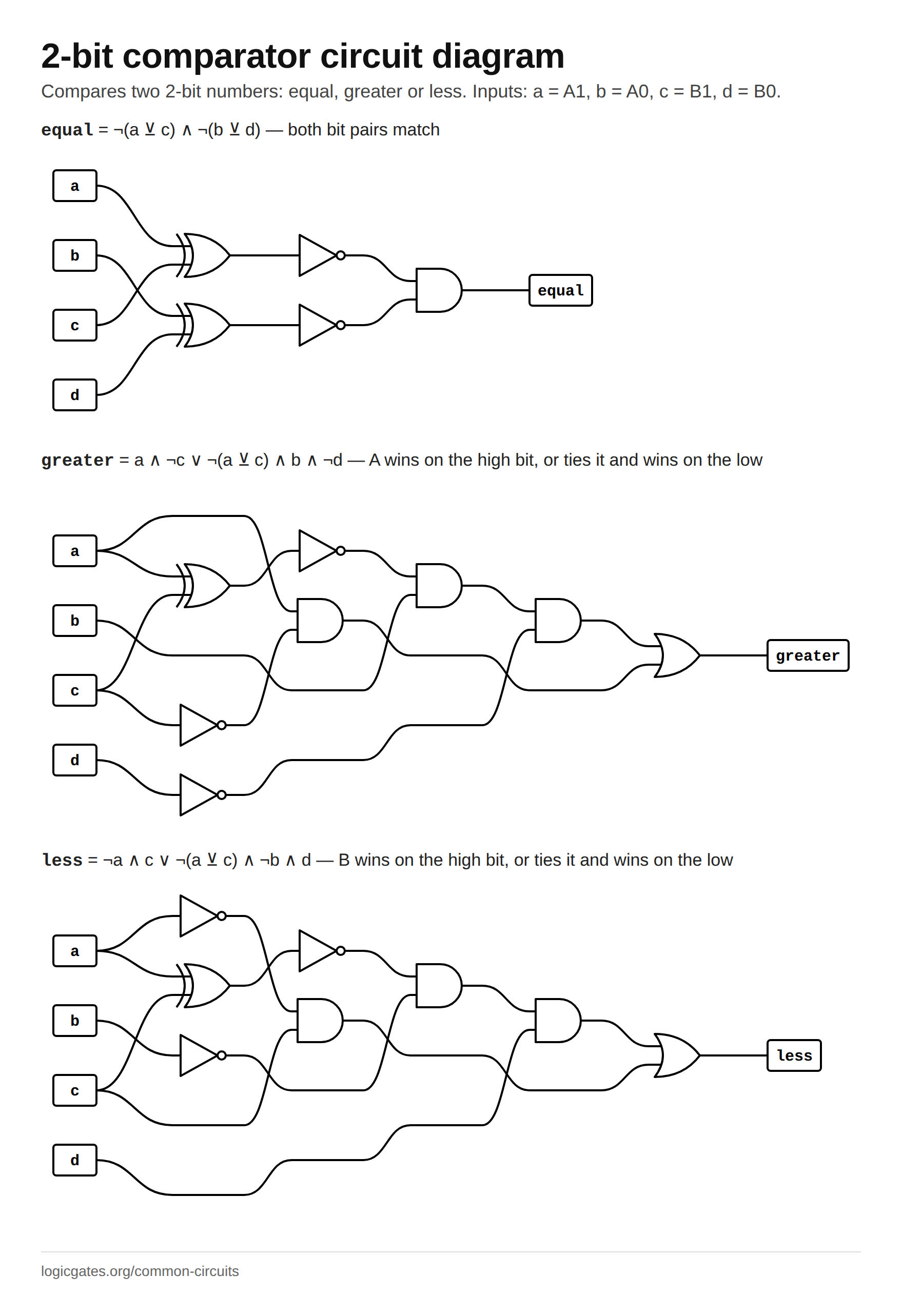
- ¬(a ⊻ c) ∧ ¬(b ⊻ d) both bit pairs match
- greater
- a ∧ ¬c ∨ ¬(a ⊻ c) ∧ b ∧ ¬d A wins on the high bit, or ties it and wins on the low
- less
- ¬a ∧ c ∨ ¬(a ⊻ c) ∧ ¬b ∧ d B wins on the high bit, or ties it and wins on the low
How it works
Comparing two bits at a time is the 1-bit comparator twice, with a rule for combining them: the high bits decide unless they are equal, in which case the low bits decide. Equality is the AND of the two per-bit XNORs. Greater is "A1 beats B1" or "the high bits tie and A0 beats B0", and less is the mirror image. Widening to more bits adds one more term per bit, each guarded by every tie above it.
Where it is used
- Branch decisions on small fields such as priority levels or opcodes.
- Detecting that a 2-bit counter has passed a threshold.
- The building block of wider comparators, which chain these so that a lower stage only decides when every stage above it reports equal.
Build it
Two XNORs for the per-bit equality, then an AND for equal and two AND-OR networks for greater and less. Check that exactly one of the three outputs is high for every one of the sixteen input combinations.
Or draw it from the expressions above with the circuit diagram generator, in either symbol standard, and export it as SVG, PNG, Verilog or VHDL.
Reference card
The diagram above as an image, black on white, for notes or a slide.
 Click to download: 2-bit comparator circuit diagram
Questions about the 2-bit comparator
How does a 2-bit comparator work?
It compares the high bits first. If A1 and B1 differ, that settles it: A is greater when A1 is 1, less when B1 is 1. If they are equal, the low bits decide the same way. Equal means both pairs match, which is the AND of two XNOR gates. Exactly one of the three outputs is high for any input.
How do you build a 4-bit comparator?
Extend the same rule: A is greater if it wins on bit 3, or ties on bit 3 and wins on bit 2, or ties on bits 3 and 2 and wins on bit 1, and so on down to bit 0. Equal is the AND of all four per-bit XNORs. The 7485 is exactly this circuit for four bits, with cascade inputs so several can be chained for wider numbers.