OR gate
High when at least one input is high.
Truth table
| a | b | Q |
|---|---|---|
| 0 | 0 | 0 |
| 0 | 1 | 1 |
| 1 | 0 | 1 |
| 1 | 1 | 1 |
At a glance
- Boolean expression
- a ∨ b
- Engineering notation
- a + b
- Inputs
- Two or more
- Output is high when
- at least one input is high
How the OR gate behaves
An OR gate outputs 1 if any of its inputs is 1, and only outputs 0 when every input is 0. This is the inclusive or: unlike everyday English, "a or b" here is still true when both are true.
Two switches wired in parallel. Close either one, or both, and the current gets through; the only way to stop it is to open all of them. OR is the parallel connection to AND's series one.
Building it from other gates
Each of these is equivalent to the OR gate. Paste any of them into the simulator with ctrl+E to see the circuit.
| Construction | Expression | Equals |
|---|---|---|
| From NAND gates | !(!(a & a) & !(b & b)) | a | b |
| From NOR gates | !(!(a | b) | !(a | b)) | a | b |
| De Morgan form | !(!a & !b) | a | b |
Reference card
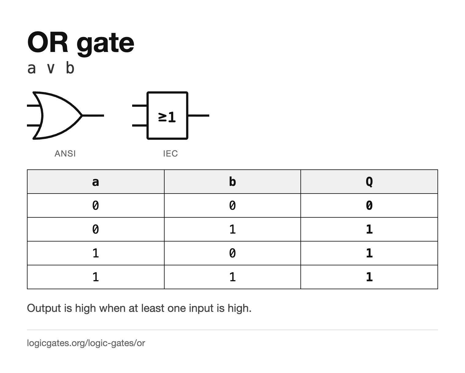
The symbol in both standards and the truth table on one image, for notes or a slide.
 Click to download the OR reference card
Where the OR gate is used
- Collecting alarm or error conditions: any one of them going high raises a single combined flag.
- Bitwise OR in software, setting bits without disturbing the others.
- Merging several requests onto one line, as in a simple interrupt system.
- Building a sum of products, where the final OR joins the AND terms together.
In the simulator
OR sits in the Logic menu next to AND, and takes a configurable number of inputs in the same way.
Questions about the OR gate
Is OR inclusive or exclusive?
Inclusive. An OR gate outputs 1 when both inputs are 1. If you want the exclusive version, which is 0 when both inputs are 1, that is the XOR gate.
What is the difference between OR and NOR?
NOR is OR with an inverted output: it gives 1 only when every input is 0.