T flip-flop
Hold when T is 0, invert when T is 1.
Live demo. Set the inputs, then clock it. Q⁺ = T ⊻ Q
Nothing clocked yet. The state only moves on an edge.
How it behaves
A single input decides whether the output keeps its value or flips it on the clock edge. That is the entire specification, and it makes the T flip-flop the natural building block for anything that counts.
Toggling is division. Tie T high and the output changes on every clock edge, so it completes one cycle for every two input cycles: a divide by two. Chain four of them and you have a counter that displays 0 to 15 in binary, which is exactly how a simple ripple counter works.
Characteristic table
What the next state is, for every combination of inputs and present state. The equation below is this table written as algebra.
| T | Q | Q⁺ | Effect |
|---|---|---|---|
| 0 | 0 | 0 | hold |
| 0 | 1 | 1 | hold |
| 1 | 0 | 1 | toggle |
| 1 | 1 | 0 | toggle |
Q⁺ = T ⊻ Q
Timing
The same behaviour in time rather than in a table. Each dashed line marks a clock cycle boundary — a rising edge, except for the last, which is just the end of the diagram — and Q only ever changes on an edge: that is what makes it a flip-flop rather than a latch. The inputs walk through every legal combination in turn, held for two cycles so you can see the response arrive a cycle late.
Reference card
The same waveform as an image, black on white, for notes or a slide.
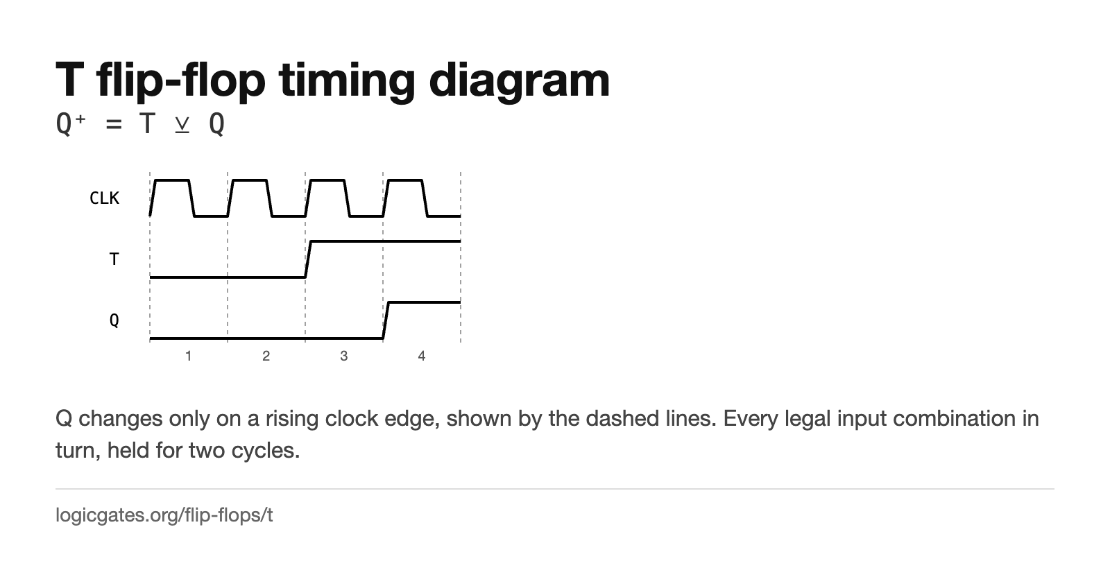 Click to download: T flip-flop timing diagram
Excitation table
The same information turned around. You know the transition you want; this says what to put on the inputs to get it. This is the table you use when designing a counter or a state machine, and the X's are what make the driving logic small.
| Q | Q⁺ | T |
|---|---|---|
| 0 | 0 | 0 |
| 0 | 1 | 1 |
| 1 | 0 | 1 |
| 1 | 1 | 0 |
An X means the input does not matter for that transition, which is a don't care when you minimise the logic that drives it.
Building one
A JK flip-flop with J and K tied together, or a D flip-flop with D = T ⊻ Q, which is one XOR gate fed from the output. The XOR version is the one you will build in a simulator.
The editor has a Delay node, which is what you need to make feedback settle predictably rather than oscillating.
Where it is used
- Binary counters: each stage toggles when the one before it falls, so the bits count up.
- Clock division, halving a frequency per stage.
- Turning a momentary button into an on/off state that survives the button being released.
- Gray code counters, where only one stage is allowed to change per step.
Questions about the T flip-flop
How do you make a T flip-flop from a D flip-flop?
Feed D from an XOR gate whose inputs are T and the flip-flop's own output. When T is 0 the XOR passes Q back unchanged and the state holds; when T is 1 it passes ¬Q and the state flips.
Why is a T flip-flop good for counting?
Because its output changes once every two clock edges, which is a divide by two. Cascade n of them and you get a counter with n bits, each stage running at half the rate of the one before it.