JK flip-flop
Set, reset, hold, and the forbidden case turned into something useful.
Live demo. Set the inputs, then clock it. Q⁺ = (J ∧ ¬Q) ∨ (¬K ∧ Q)
Nothing clocked yet. The state only moves on an edge.
How it behaves
J sets and K resets, exactly like S and R. The difference is the case where both are high: instead of being forbidden, it toggles the output. That makes every one of the four input combinations meaningful, which is why the JK was for a long time the general purpose flip-flop.
Take an SR flip-flop and feed the outputs back into the input gates, so the circuit knows its own state. Now "set" can only act when the output is 0 and "reset" only when it is 1, which is what removes the contradiction. The freed-up combination then toggles on its own: the same feedback that removed the contradiction routes the state back to the opposite input, so the toggle costs nothing extra.
Characteristic table
What the next state is, for every combination of inputs and present state. The equation below is this table written as algebra.
| J | K | Q | Q⁺ | Effect |
|---|---|---|---|---|
| 0 | 0 | 0 | 0 | hold |
| 0 | 0 | 1 | 1 | hold |
| 0 | 1 | 0 | 0 | reset |
| 0 | 1 | 1 | 0 | reset |
| 1 | 0 | 0 | 1 | set |
| 1 | 0 | 1 | 1 | set |
| 1 | 1 | 0 | 1 | toggle |
| 1 | 1 | 1 | 0 | toggle |
Q⁺ = (J ∧ ¬Q) ∨ (¬K ∧ Q)
Timing
The same behaviour in time rather than in a table. Each dashed line marks a clock cycle boundary — a rising edge, except for the last, which is just the end of the diagram — and Q only ever changes on an edge: that is what makes it a flip-flop rather than a latch. The inputs walk through every legal combination in turn, held for two cycles so you can see the response arrive a cycle late.
Reference card
The same waveform as an image, black on white, for notes or a slide.
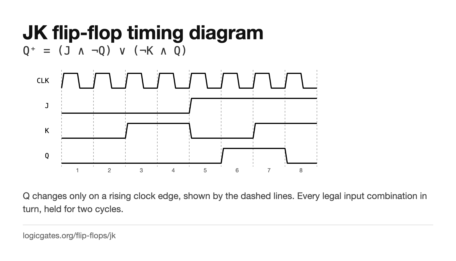 Click to download: JK flip-flop timing diagram
Excitation table
The same information turned around. You know the transition you want; this says what to put on the inputs to get it. This is the table you use when designing a counter or a state machine, and the X's are what make the driving logic small.
| Q | Q⁺ | J | K |
|---|---|---|---|
| 0 | 0 | 0 | X |
| 0 | 1 | 1 | X |
| 1 | 0 | X | 1 |
| 1 | 1 | X | 0 |
An X means the input does not matter for that transition, which is a don't care when you minimise the logic that drives it.
Building one
An SR flip-flop with the outputs fed back: J is ANDed with ¬Q and K with Q before they reach the set and reset inputs. It must be edge triggered, because a level triggered version with J = K = 1 would toggle continuously for as long as the clock stayed high.
The editor has a Delay node, which is what you need to make feedback settle predictably rather than oscillating.
Where it is used
- Ripple counters, by tying J and K high so the flip-flop toggles on every edge.
- State machines, where the don't cares in its excitation table often make the driving logic smaller than a D would.
- Shift registers and frequency dividers.
- Any place you want set, reset and toggle available from one part.
Questions about the JK flip-flop
What do J and K stand for?
Nothing agreed on. The most repeated story is that they honour Jack Kilby, though it has never been firmly established. Treat them as arbitrary names for the set and reset inputs.
What happens when J and K are both 1?
The output toggles on every clock edge. That is the whole reason the JK exists: the input combination that an SR flip-flop forbids is put to work as an invert instruction.